DASL (DAU Automation Specification Language) is a formal specification language for industrial automation, which allows us to use TLA+/TLC to reason about the specification and to generate Go code implementing the formal specification. The formal DASL specification is embedded in code blocks inside markdown files allowing us to describe our formal specification in natural language in one document.
DASL is made with gogll
Background
When developing complex systems we are always confronted by the problem of specifying the system to be built in such a way that we can reason about its behaviour without drowning in implementation detail. This requires an abstract description that is suitable for the kind of reasoning required.
If we achieve such an abstract description of the system we are left with the problem of mapping the specification into an implementation that faithfully maintains the semantics of the specification. If we also manage that successfully we are immediately confronted with the problem of maintaining consistency between the specification and the implementation during the inevitable scope creep and maintenance of the system. And usually we also need a description of the system in natural language, for other people’s understanding, which must also remain consistent with the formal specification and the implementation. All this is hard to achieve using unrelated specification-, programming and documentation tools.
There are successful examples of formal specification and code generation. We can specify a language formally in a grammar and generate a parser and scanner for it from the grammar (e.g.: gogll). But this is specific to language problems and does not help when we have to describe concurrent and distributed systems.
CSP [Hoare 85] is a formal language of concurrent systems developed by Tony Hoare. It led to the development of the INMOS Transputer - a hardware implementation of CSP that allowed processes on different processors to communicate over channels. But you had to program it in OCCAM, which is not a very abstract language.
Statecharts [Harel 86] are a powerful visual formalism for complex systems, which was used to generate implementation code. They were adopted as the state machine notation in UML. But without graphics support a statechart very quickly becomes over cluttered for anything more than a trivial specification.
The most enduring and useful formal specification method for concurrent systems has been Leslie Lamport’s TLA+ and the TLC toolkit [Lamport 2003]. TLA+ has be used successfully to model complex software and hardware problems. The problem is that TLA+ is very general and the problem of mapping the formal specification faithfully to an implementation remains.
Our Problem
When we were confronted by a complex industrial automation problem we looked for a method to specify the system in such a way that we could reason about its behaviour before it was implemented in hardware and software by a team of Mechanical-, Electronic- and Software Engineers.
Our problem was to retrofit electronic instrumentation to millions of existing products and mapping the instrument to the product, all under control of cloud software in Amazon Web Services (AWS).
The basic components of our automation system are: an articulated arm robot; two segments of automated conveyor (input and output); a clamping system to hold the work on the last segment of the input conveyor while the robot performs the installation. There are also several sensors: to detect the presence/absence of a product on the last segment of the input conveyor (the robot’s worktable) and on the first segment of the output conveyor; readers for the ID of the product and the instrument: LF and HF RFID/NFC; barcode and QR code. The required behaviour of the complete system depends on the correct synchronisation of the actions of all these components, as well as handling the errors that my occur.
When we failed to find any suitable existing tools we set out the main requirements of such a specification system:
A formal language in which to express the modular decomposition of a concurrent industrial automation system consisting of autonomous modules which must synchronise their actions. The specification must include the required behaviour of the system, the synchronisation constraints on the modules and the handling of errors.
A formal method to reason about the system and to assert/prove invariant and temporal characteristics required of the system.
To use all available technology to assist in the correctness and robustness of the implementation.
DASL: The Specification Language
The initial version of the DASL language attempted to implement the semantics of statecharts as defined in [Harel 96]. We soon realised that we need only a subset of these semantics to fully specify our automation problems, which led to the current version of the DASL language described here.
The approach in DASL is as follows:
Specify the modular decomposition of the system top-down. The top-level DASL module is a specification of the processes that are the digital twins of each hardware component of the system.
We can specify a complete system in one file, or separate modules in separate files.
The following is the top-level specification of a simple example, which declares the concurrent modules (processes) of the system. The state machine that implements the complete specification will be generated in a set of Go language packages matching the processes.
The
systemdeclaration also registers the interface modules that will handle the communication between the generated automation control state machine and the hardware components. These interface modules are hand coded. DASL generates a specification for the interface between each interface module and the state machine.We chose to specify the processes of this example in external files for clarity of this level of the specification.
gopkg "github.com/xxx/Simple/go"

system Simple {
    process external Robot // The articulated arm robot
    process external InputConveyor
    process external OutputConveyor
    process external IDMapper
    process external Clamps

    register component robot
        "github.com/xxx/go/components/impl/robot"
    register component inputconveyor
        "github.com/xxx/go/components/impl/inputconveyor"
    register component outputconveyor
        "github.com/xxx/go/components/impl/outputconveyor"
    register component idmapper
        "github.com/xxx/go/components/impl/idmapper"
    register component clamps
        "github.com/xxx/go/components/impl/clamps"
}
The function of the automation system is to install an instrument into a work item.
The system consists of an articulated robot, automated input and output conveyors, an ID mapper with sensors to read the IDs of the work and instrument and a set of clamps that hold the work in place for the robot to operate on.
Specify the state machine in detail for each process.
The following example is the state machine specification for the
IDMapperprocess. It reads the IDs of the work and instrument and posts the mapping of the two to the backend system.IDMapper { Ready init { [Robot.PickInstrument] -> Reading }The
initdeclares thatReadyis the initial state of theIDMapperprocess.In this state we wait until the
Robotprocess is in thePickInstrumentstate when we transition to theReadingstate of theIDMapperprocess.Reading(workID, instrumentID) { on entry do { readWorkID readInstrumentID } workID -> skip instrumentID -> skip [workID & instrumentID] -> Read(workID, instrumentID) timeout 10s -> Error(workID, instrumentID) }The
Readingstate has parameters,workIDandinstrumentID. Since the parameters were not passed toReadingthey must be collected in this state.When the
Readingstate is entered the system calls thereadWorkIDandreadInstrumentIDactions of theidmappercomponent registered insystemabove. These actions will be executed asynchronously and the results will be reported to the state machine as events:workIDandinstrumentID.Exit actions may also be declared, which are executed when we transition out of a state.
When we receive a
workIDorinstrumentIDevent in this state, the event is stored in its respective state parameter and no state transition is exectuted (skip).When both parameters have been collected we execute a state transition to the
Readstate, passing the collected parameters to the new state. This conditional transition is guarded by the[workID & instrumentID]condition, which waits until both parameters have been assigned before enabling the transition to the next state.If one or both of the ID reads fail the timeout will occur and we will transition to the
Errorstate.Read(workID, instrumentID) { [Robot.Inserted] -> Posting(workID, instrumentID) timeout 10s -> Error }In the
Readstate we wait until theRobothas successfully inserted the instrument into the work before transitioning to thePostingstate.Posting(workID, instrumentID) { on entry do postMapping(workID, instrumentID) mapped -> Mapped timeout 10s -> Error }On entering
Postingtheidmapperinterface component posts the mapping to the backend and we wait for amappedevent confirmation from the backend.Mapped{ [Clamps.Open] -> Ready timeout 10s -> Error }With mapping complete we wait in
Mappedfor the clamps to open before we are ready to read again.Error(workID, instrumentID) { reset -> Ready } }In the
Errorstate the system logs the error and waits for aresetcommand from the user control interface.In this way we specify the behaviour of all the processes in the system and how they synchronise by waiting on specific states in the other processes.
Using TLA+ to prove statements about the specification
The DASL specification of our system cleanly separates the concerns of each of the autonomous modules of our system, clearly describes the behaviour of each process and how processes synchronise by conditioning on the state of other processes. It also cleanly separates the concurrent control system from the sequential interface modules of each hardware component in the system. This makes it easy to reason about the system.
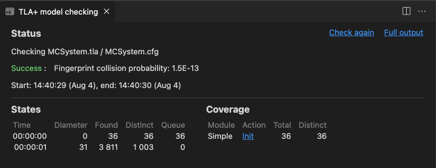
The DASL compiler generates a TLA+ specification for our DASL specification. The TLC model checker gives us the following output showing that it found no errors in the specification.
If we introduce an error into the IDMapper.Read state as follows,
    Read(workID, instrumentID) {
        [Robot.Inserted] -> Posting(workID, instrumentID)
//      timeout 10s -> Error
    }
the model checker finds a deadlock in the system after a sequence of 15 steps:

snip
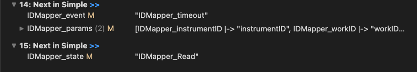
TLC also gives us the sequence of steps that led to the deadlock.
Errors like these are very hard to find because they require particular sequences of events to occur. We get this kind of quality assurance for free by using DASL and TLC.
But we can go further and specify TLA+ assertions about the system that we require to be true under all conditions. For example:
Safe == ~(Robot_state \in {
                                "Robot_CutHole",
                                "Robot_Weld",
                                "Robot_Install"
                            } /\
            OutputConveyor_state = "OutputConveyor.Full")
This TLA+ assertion states that the robot may never be in one of the states {CutHole,Weld,Install} while the first segment of the output conveyor is occupied. This is because the robot does not have sufficient space to operate if the first segment of the output conveyor is occupied.
It is a safety specification, which TLC model checker will find if it is violated in any possible behaviour of the system under this specification.
We can also use TLA+ to verify temporal assertions about the the system, for example:
Progress ==
    InputConveyor_state = "InputConveyor_Full" ~> Robot_state = "Robot_Installed"
This asserts that every time the robot’s worktable becomes occupied leads to the robot having completed the installation.
The model checker tells us that this temporal assertion is violated when errors occur and gives us the sequence of steps that leads to the violation.
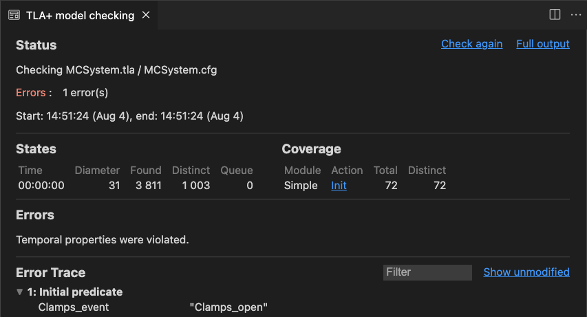 snip
snip

The reason is that our temporal assertion is too strong. If an error occurs in
any of the processes during the installation the the Robot process will not
reach the Installed state.
We can make the weaker statement
Progress ==
    InputConveyor_state = "InputConveyor_Full" => <>(Robot_state = "Robot_Inserted")
that work on the worktable implies that eventually the the instrument will be installed.
This statement satisfies the specification and the model checker finds no temporal violations.
Specification compliant implementation in Go
We chose Go as our implementation language for a number of reasons:
- Go very efficiently supports lightweight concurrent processes that communicate over channels.
- Go is a strongly typed language, which means that the compiler will find errors that would otherwise have caused runtime errors in languages such as Erlang or Python.
- Go compiles to very efficient native code, which means we need only one programming language for all our software.
The Go implementation (generated by DASL) of the specification has a master module that sequences all the events coming from the environment. This means that the state machine makes an atomic transition for every event and every condition that becomes true and that the semantics of the TLA+ specification are maintained.
For every event received the master module calls the event handler of the
state machine of the relevant process. The event handler generated for the
Clamps process by DASL is shown below.
// Event is called on a process when an event arrived for it to process.
// The process completes the state transition appropriate for the event.
func (proc *IDMapper) Event(e events.Event) {
    switch proc.State {
    case IDMapper_Ready:
        switch e.(idmapper_events.Event).Type() {
        default:
            proc.specError("Unexpected event %s in state IDMapper.Ready", e)
        }
The event handler switches on the current state of the process. In the
IDMapper.Ready state above the state machine waits for the
Robot.PickInstrument state and therefore any event received in this state
is an error.
    case IDMapper_Reading:
        switch e.(idmapper_events.Event).Type() {
        case idmapper_events.InstrumentIDType:
            proc.instrumentID = e.(idmapper_events.Event)
            // skip
        case idmapper_events.TimeoutType:
            proc.nextState(IDMapper_Error)
        case idmapper_events.WorkIDType:
            proc.workID = e.(idmapper_events.Event)
            // skip
        default:
            proc.specError("Unexpected event %s in state IDMapper.Reading", e)
        }
In IDMapper.Ready we assign the ID events to state parameters and make no
state transition.
snip
    case IDMapper_Posting:
        switch e.(idmapper_events.Event).Type() {
        case idmapper_events.MappedType:
            proc.nextState(IDMapper_Mapped)
        case idmapper_events.TimeoutType:
            proc.nextState(IDMapper_Error)
        default:
            proc.specError("Unexpected event %s in state IDMapper.Posting", e)
        }
    }
In IDMapper.Posting we make state transitions on the mapped event and
timeout.
snip
Every process has a nextState function that executes the entry and exit
actions of the state when making the state transition. The nextState function
of the IDMapper process is shown below.
func (proc *IDMapper) nextState(nextState IDMapperState) {
    proc.exit()
    proc.State = nextState
    proc.enter()
}
The nextState function first calls the exit action of the current state;
then it changes state and calls enter on the next state.
After an event has been handled by one process, the main module calls the
Transition method on all other process to make any conditional transitions that
may have become possible after handling the event. The Transition method of
the Clamps process is shown below.
// Transition is called on all other processes after an event has been handled
// by one of the processes.
func (proc *IDMapper) Transition() {
    switch proc.State {
    case IDMapper_Ready:
        switch {
        case RobotProc.State == Robot_PickInstrument:
            proc.nextState(IDMapper_Reading)
        default:
            // ignore
        }
The case above shows the conditional transition
[Robot.PickInstrument] -> Reading
in IDMapper.Ready
    case IDMapper_Reading:
        switch {
        case proc.workID != nil && proc.instrumentID != nil:
            proc.nextState(IDMapper_Read)
        default:
            // ignore
        }
The case above shows the conditional transition on state parameters
[workID & instrumentID] -> Read(workID, instrumentID)
in IDMapper.Reading.
snip
DASL generates an interface specification for every interface module. The interface for the idmapper interface module is shown below.
/ Package idmapper was generated by DASL.
// Do not edit.
package idmapper

import(
    idmapper_events "github.com/xxx/Simple/go/events/idmapper"
)

// Actions is the set of functions called by the state machine on this component.
// Components must implement all functions.
type Actions interface {
    PostMapping(workID idmapper_events.Event,instrumentID idmapper_events.Event)
    ReadInstrumentID()
    ReadWorkID()
}
The interface module for the idmapper component must implement the functions
of the Actions interface and
send events from the idmapper sensors and backend system
back to the control state machine.
All events from all interface modules are sent on the same channel in the main module:
var eventChan = make(chan events.Event, 256)
The Event type definition is generated in an events package by DASL:
// package events was generated by DASL. Do not edit.
package events

type Event interface{
    isEvent()
}
type Event interface{
    isEvent()
}
DASL generates an interface for the events of every hardware interface. The package for the idmapper interface is shown below.
// package idmapper was generated by DASL. Do not edit.
package idmapper

type Event interface {
    isEvent()
    Type() EventType
}

type EventType int

const(
    InstrumentIDType EventType = iota
    MappedType
    ResetType
    TimeoutType
    WorkIDType
)
The Event interface must be implemented for every hardware
interface module.
Summary
DASL provides a powerful notation for specifying and reasoning about complex industrial automation systems.
It allows formal analysis of the correctness of the specification by proving theorems about in in the TLA+ specification generated by DASL. By default the TLC model checker will find any deadlock lurking in the specification.
The TLA+ specification formally states the semantics of the specification.
Once a specification is arrived at that adequately describes the automation problem and we have verified its correctness with TLA+/TLC, DASL generates the state machine implementation of the specification in Go.
This ensures that the specification and implementation are always in sync and that the implementation is faithful to the semantics of the specification.
Since the DASL specification is made in markdown files we can write our descriptive documentation as part of the formal specification.
We are happy that we have tamed the complexity of specifying our industrial automation problem. The solution is scaleable and can be easily fitted into a standard automation architecture, such as the holonic PROSA architecture [Cardin 2018].
We intend to make DASL available as open source in the near future.
Future Work
The current version of DASL is sufficient for our immediate needs. In future we will look at collecting arrays of state parameters as well as counting in order to use the technology for communication protocols and other embedded software.
Bibliograpy
- [Cardin 2018] Olivier Cardin, William Derigent and Damien Trentesaux. Evolution of holonic control architectures towards Industry 4.0: A short overview. arXiv:1810.09109
- [Harel 86] David Harel. STATECHARTS: A VISUAL FORMALISM FOR COMPLEX SYSTEMS. Science of Computer Programming 8 (1987)
- [Harel 96] David Harel and Amnon Naamad. The STATEMATE Semantics of Statecharts. ACM Transactions on Software Engineering and Methodology Vol 5 No 4 October 1996
- [Hoare 85] Hoare C.A.R. Communicating Sequential Processes. Prentice Hall 1985
- [Lamport 2003] Leslie Lamport. Specifying Systems. The TLA+ Language and Tools for Hardware and Software Engineers. Addison Wesley 2003